| |
|
The above articles identify a class of orbits giving best coverage of the magnetotail, and also suggests that they required a launch not from Cape Canaveral (latitude 28.5 N) but from a site close to the equator, e.g. Kourou (lat. 5 N). It was pointed out by Steven Hughes of Flight Dynamics Branch, NASA Goddard Space Flight Center that a relatively modest apogee burn also makes such orbits accessible from Cape Canaveral. The way this is done is explained below.
|
- The two articles listed above have focused on near-equatorial orbits with low perigee and with apogee of 20-25 RE (Earth radii). They found that an orbit giving both good coverage of the midnight plasma sheet and tolerably short eclipses had (i) inclination 13-180 to the ecliptic and (ii) apogee at midnight around the summer solstice. Furthermore, (iii) its orbital plane gave the satellite at apogee a velocity tangential to the ecliptic, helping it stay in the plasma sheet, rather than cut across it.
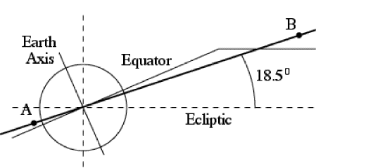
That conclusion remains valid. A side view of the orbit is shown in Figure #1 below, which reproduces Fig. 4b of the first article

Figure #1 Point A in this drawing is perigee (just above Kourou), B is apogee, the solid line perpendicular to the Earth axis is a cut through the equatorial plane, and its continuation parallel to the ecliptic represents a cut through the plasma sheet (not to scale). The "hinge" between it an the equatorial plane is actually at a distance of about 8 RE and is in reality a smooth curved transition, not a sudden kink.
|
The Sun is in the plane of the drawing far to the left, as befits the summer solstice. At that time, the apogee B is in or near the midnight plasma sheet, yet far from the plane of the ecliptic (broken line). Because the satellite spends relatively long times around its apogee, were B on the ecliptic or near it, it would be spending long times in the Earth's shadow, getting severely chilled.
-
The satellites are first launched into a circular parking orbit, from which the last stage is later fired, at a point which (neglecting the duration of the firing itself) becomes the perigee point A.
In Figure #1, A is in the (Z, Ze) plane, containing the Earth axis Z (solid line, labeled) and the perpendicular Ze to the ecliptic (broken line, not labeled). Then and only then is perigee in the midnight plasma sheet during the summer solstice, the way the drawing shows it.
In Figure #1, A is in the (Z, Ze) plane containing the Earth axis Z (solid line, labeled) and the perpendicular Ze to the ecliptic (broken line, not labeled). Then and only then is perigee in the midnight plasma sheet during the summer solstice, the way the drawing shows it.
A simple way of reaching the desired orbit is to have the parking orbit in the same plane as the final one. In Figure #1 both orbits would be viewed edge-on, represented by overlapping straight lines. The upper stage is fired eastward (upwards from the plane of the drawing) when the rocket reaches point A, in same (Z, Ze) plane; A could as well be the launch point, because there, too, the velocity is directed eastward.
- The orbital situation in Figure #1 is ideal, but a less than ideal condition is still acceptable. That happens in Figure #2a: the long axis AB of the orbital ellipse is the same as before, but the orbital plane of the ellipse is rotated by some angle around AB

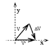
Consider the motion at the apogee point B in the above drawing. Figure #2b defines (x,y) coordinates in a plane passing B and perpendicular to the line of apsides; the notation (x,y) is unrelated to any celestial or terrestrial coordinate system, except that x is perpendicular to the plane of the Figure #1 (the (Z, Ze) plane) and points in the direction in which we want the rocket at B to move.

|
Let V be the actual velocity of the satellite at apogee A in Figure #2, meeting the plane of the paper at some slant angle, and let V' be the same velocity but perpendicular to the plane of the drawing--in the direction of the apogee velocity in Figure #1, i.e. the velocity which we want the satellite to have at apogee. Obviously, all we need is add a velocity ΔV . This can be calculated and is relatively modest--V is about 500 m/s, ΔV typically half as much.
|
-
The next goal is therefore, how to reach an orbit such as the one in Figure #2b with a launch at Cape Canaveral. In what follows we assume that we seek an orbit with perigee A at the latitude of Kourou, 50 N; a similar procedure can be devised for other latitudes.
In Figure #4 (to the right) the equator (solid) is horizontal, not as in Figures #1 and #2a. Kourou (marked K) is slightly above it, as is appropriate for latitude 50 N, while Cape Canaveral is marked C.
 The broken oval is some circular parking orbit launched from Cape Canaveral (here slightly north of the ecliptic--straight broken line). Any such orbit covers geographic latitudes from 28.50 N (latitude of Canaveral) to 28.50 S, and it crosses 50 N twice--once when south of the ecliptic (open circle in the drawing), once north of it. If we fire the last stage from the first of these, apogee is north of the ecliptic, just as we need.
The line of apsides AB then looks like the one in Fig. #2, but it still does not lie in the (Z, Ze) plane. However, we remain free to choose the time of launch. In any 24 hours, Cape Canaveral makes a 3600 rotation around the Earth's axis, so does the broken oval and the launch point marked on it . At some time in its rotation, that point crosses the (Z, Ze) plane: firing the upper stage at that moment ensures a line of apsides like the one in Figure 2a. A final rocket firing at apogee then leads to the orbit of Fig. #1.
Back to the "Profile" Index Page
Back to the "Exploration" Index Page
|
|