(E17) Capacitance and stored Electric EnergyAs already noted, even large capacitors cannot store much electric charge. A 100-watt lightbulb draws about 0.9 amperes, i.e. a charge of 0.9 coulomb per second: a capacitor storing even 1% of this charge at 110 volts would have to be extremely large. Compare this to a car battery, whose specifications typically promise over 100 ampere-hours! Still, storage of charge implies the storage of electrical energy. A storage battery, in contrast, stores chemical energy, which can be converted to electrical if the need arises: it is not the same thing. A capacitor delivers all of its energy much more rapidly. The unit of capacitance is named farad, after Michael Faraday, whose work will be described in a later section. A capacitor of 1 Farad charged to 1 volt holds 1 coulomb--when charged to 20 volts, 20 coulombs, etc. You will not encounter capacitors that big: practical units are more likely to be rated in microfarads, millionths of a farad, or even picofarads, millionths of a microfarad. The word "micro" (Greek for "small") is usually used to denote "a millionth" of a quantity (just as "milli" means "a thousandth"). The word is commonly denoted by the Greek letter mu or μ (lower-case Greek m). A microfarad is then abbreviated μf, a picofarad pf or μμf. The DC power supply of an old-style radio receiver may have a 5-50 μf capacitor, while the circuitry itself may have component capacitors of 500 μμf or smaller. Radio frequency is quite high, so even a small capacitor is not much of an obstacle. As noted, a capacitance of C farad, charged to a voltage of V0 volts, contains a charge Suppose a capacitance C is charged to voltage V0: its charge is then How much energy does such a device store? Suppose we discharge it in one second. Then since amperes = coulombs/second, the average current over that second (averages denoted here by curly brackets) is then The average voltage is not V0, because as charge drains away, the voltage drops. Dividing both sides of the first equation above by C (and switching sides) 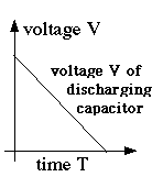
showing that as the charge drains away, starting with Q0 and ending with zero, the voltage also drops steadily, from V0 to zero (drawn graph) We may estimate (and a rigorous calculation confirms it) that the average voltage is half the peak value
The average power Substituting Q from the top equation The energy E = Wt is power multiplied by time. Since the discharge lasts one second, we get 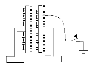
What is going on here?How can parallel plates insulated from each other hold much more charge? Essentially, the positive charge on one attracts the negative charge on the other, enabling it to hold more. If one plate is given (say) a negative charge and the other one is connected to the ground, equal and opposite (that is positive) charge will be drawn up to it from the ground. If later we disconnect the ground, that plate will remain positively charged.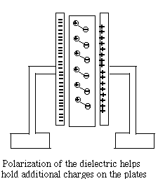
The insulator between the plates (the "dielectric material") also plays an important role. Its atoms too contain negative electrons and positive nuclei, though those charges cannot move freely, as they might do in a conductor. However, the electric forces (or "electric field") in the gap between the two plates cause the distribution of charges to deform--positive charges may shift slightly towards the negative charges outside, while negative charges back away a little. The electric deformation of atoms of the insulator shields the electric force inside the material, making it weaker there, and may enable the plates to hold several times more charge. Thus the capacitance of a capacitor is multiplied by the "dielectric constant" ε (Greek epsilon) of the insulating material between them. One material of exceptionally high dielectric constant ε=81 is water, which explains why it is able to loosen the bonds in ionic compounds, held together by electric attraction. That however only holds on the atomic scale, while water in a cup (even distilled water) is not an insulator but a conductor, because at least some of its molecules are constantly dissociating. The Neon Flasher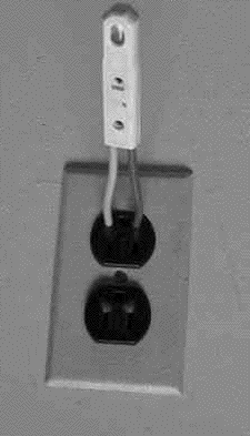 With the help of a capacitor a very simple flashing light may be constructed, based on the neon light, a small lightbulb filled with low-pressure neon gas. The light of a neon light, like that of a fluorescent light fixture, is produced by an electric current flowing across the gas-filled gap, carried by a plasma, a gas in which some electrons (at least) are detached from their atoms (which are left with positive charges). The voltage across the gap accelerates some electrons, which then can "ionize" some more atoms (separating electrons from them) and increase the current. Ultimately however they are recaptured, while other electrons are "bumped up to a higher energy level" of their atom. When they return to the lowest "ground level" of energy (in a fraction of a millionth of a second, usually), or are recaptured, they give up their extra energy as light.
You should not be surprised that such conduction does not obey Ohm's law, according to which the current is proportional to the voltage across the gap. (Indeed, Ohm's law is not a fundamental law of nature--only an approximation to the behavior observed in many everyday electrical conductors). When the voltage is low--say below 70 volt--no appreciable current flows at all. Some ions may form spontaneously (from surrounding radioactivity and cosmic rays), but they recombine before the voltage accelerates them sufficiently to create more ions, and the current they carry across the gas is tiny. However, once a certain threshold value is passed--depends on the device, but 70 volt is typical--electrons are accelerated enough between collisions to free up additional electrons, and the whole process turns into an unstable "avalanche." The neon tube then becomes a "greedy conductor," drawing more and more electrons until some limit is passed--e.g. it gives one very bright flash and then stops working altogether. That can be prevented by placing a large resistance--say, 10 million ohms--in the circuit of the lightbulb, which limits the current to microamperes, still enough to produce visible light. Lamps with such resistance built-in and two insulated probe wires sticking out are sold as neon tube testers, to safely check whether a circuit is "live" (connected to the power) or "dead." You can stick both wires into an electric outlet and see if the lamp lights up, showing the outlet is "hot." To tell which of the sides of the outlet is hot and which one is grounded, stick one contact of the tested in the outlet and hold the other between two fingers, connecting it to the ground. If outlet connection leads to the "hot" side, the lamp will lights up; an electric current then flows through your fingers to the ground, but it is so small you will not notice it. 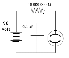
A crude oscillating circuit can be made by connecting a capacitor in parallel with the lamp, one side branching off from each side of the lamp, and with a large resistor limiting the current (illustration; obtain the neon lamp separately--the one in the neon tester also has a big resistance built-in). The instant the circuit is connected to a source of DC voltage--say, 100 volts--a current will flow through the resistor to the branch-off points. Initially, the capacitor will grab it all and the light will not flash.
Once the capacitor is charged to (say) 70 volts, the lamp flashes as charge begins to flow through it, a very short flash. Soon, however (say, when the capacitor voltage falls to 60 volts), the lamp goes out and the charging resumes. Thus the lamp will oscillate between 60 and 70 volts. The wave form is very similar to a sawtooth: when the discharge starts, a rapid "avalanche" of current quickly drains charge down to the cut-off (say, 60 v) and creates a flash of light. Then, however, the current stops while the capacitor charges back to the "ignition voltage" and the process repeats, again and again.
If the resistance R is measured in ohms and C in farad (or else, R in megohms and C in microfarad), then T is in seconds. The actual duration of each oscillation depends also on the voltage supply and on the ignition and extinction voltages of the neon discharge. But in practice, it will be proportional to RC--say, 0.1 RC. Neon lights with big resistors are also attached to "power strips" combining outlets, or to other electric devices, to show if they are connected or not (running them takes very little energy). They tend to flicker, and you might notice the flickering is slower in a dark room--perhaps because electrons ejected by visible light help start the discharge.
An electronic flash on a photographic camera also discharges a capacitor through a gas plasma--in this case, the preferred gas is xenon. The charge is generated by a small circuit powered by a dry cell, connected to a transformer: once the voltage needed for a discharge is reached, the charging stops, and the capacitor is then discharged when a switch in the camera is closed.
|
|
Next Stop: E18. Pumping Volts
Home Page "All Things Electric and Magnetic"
Author and Curator: Dr. David P. Stern |
