(E23) GalvanometersThe Tangent GalvanometerThe simplest and earliest method of measuring electric current uses the tangent galvanometer. A flat coil of insulated wire is wound on a rigid frame, held by a stand in a vertical plane (like a wall). In the empty space in the middle of the coil, a magnetic compass is placed, and initially the coil is lined up so that its plane is in the north-south magnetic direction, the same as the magnetic needle.
Now insert the coil in the circuit being measured. The magnetic field of the current then tries to swing the needle 90 degrees, to point perpendicular to the coil. The position at which it then settles is a balance between the north-south field of the Earth and the east-west force of the coil. The reading is most accurate if the angle is close to 45 degrees: If the effect of the coil overwhelms that of the Earth (large deflection), accuracy is poor; if the resistance R of the coil is know, better accuracy is achieved by adding a known This early instrument was not too practical, though students in labs still practice with it. It depends on the Earth's magnetism (whose accurate measurement was a separate task--first achieved by Gauss), which changes with location and is usually off-horizontal, its sensitivity depends on the size of the coil, and the current being measured still requires a calculation. Still, it provided an early application of Oersted's discovery. Measuring the Magnetic ForceThe force between two very short current segments dL1 and dL2 separated by a distance r decreases like 1/r2
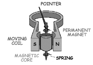
Ampére actually measured the force between parallel currents, by comparing it against known weights in an ingenious "Ampére Balance". An instrument based on this force is the moving-coil galvanometer or D'Arsonval galvanometer, used to measure currents and voltages. 
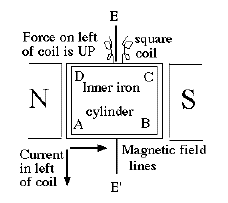
Its main components (be sure to identify the main ones before continuing!) are a strong permanent U-shaped magnet with concave pole-pieces and a small rectangular pivoted coil ABCD, around which fine insulated wires are wound. The coil itself is shaped like a small flat box without top or bottom, and the pivot EE' crosses its middle, allowing it to rotate (to some extent) in the space between the pole pieces. Other parts are insulated wires connected loosely to the coil (near the pivot, so as not to interfere with rotation), a pointer attached to the axle, with its tip in front of a dial indicating the current strength, a thin spiral spring defining the rest position of the pointer, and a small peg at the edge of the dial, stopping the pointer from moving too far--within (typically) 40-80 degrees of its rest position. The concave pole-pieces end just short of the coil, and they channel the magnetic field lines to be perpendicular to the coil in any of its positions. A cylinder of soft iron fills most of the space inside the coil and helps guide the magnetic field lines (and give more inertia to the coil). 
The operation is best understood if the rotating coil is viewed from above; let the current flow around the frame, in the direction (say) from A to B. With the magnet's polarity as drawn, by Faraday's rule of the right hand the magnetic force on the current will lift side AD and push down side BC. Since these are on opposite sides of the axis, the net effect would be to rotate the frame and its attached pointer, until the resistance of the spring stops it, at a position depending on the strength of the current. The forces on sides DC and AB do not contribute any rotation, they are parallel to the axle (plus, the currents are opposite so their forces cancel). A sensitive galvanometer is useful for measuring either currents ("ammeter") or voltages ("voltmeter")--and the higher its sensitivity, the less it interferes with the circuit where measurement is made. 
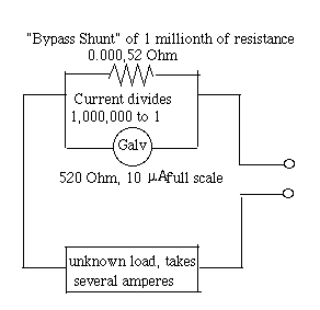
Suppose the full deflection corresponds to 10 microamperes (μA).
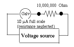
On the other hand, suppose voltage between two points is measured. The instrument is connected "in parallel" between those points (DRAWING) and includes a large resistor. The resistor greatly limits the current drawn from the main circuit, and thus minimizes the interference generated by the measurement. 
For instance, suppose our galvanometer with full deflection at 10 μA) has an added resistor of 10,000,000 Ω ahead of it. Now a voltage of 100 Volt will create a full-scale deflection; 20 volt gives a deflection of 1/5 of the dial, and so forth. The above are the most traditional uses, and a laboratory "multimeter" will have a master switch to choose resistors in series or parallel, multiplying the dial's range by various powers of 10. It will also have a rectifier and filter for measuring AC, also internal batteries for measuring resistance, with appropriate settings of the master switch, and insulated cables for connecting it. This design, from the 19th century, is still widely used, although electronic multimeters are also being sold, based on solid-state devices and probably more rugged. Afterthought: Electric MotorsSuppose we modify the instrument: omit the needle, the dial and its limiting peg, and attach the coil firmly to the axle. Would this create an electric motor?No, not yet... but we are getting close! The wires leading to the coil should not get twisted, so they can't lead simply to the outside. Instead, one may cover a section of the axle with an insulating cylinder, and on it place two metal rings, each divided in half by two small gaps. The halves on one ring are connected to two ends of the coil in one order, on the other ring, in opposite order, and small leaf springs that brush against the rings connect them to a battery. Suppose the coil is connected so that the magnetic force rotates the axle clockwise (viewed from an end of the axle chosen as reference). When the wires are pulled towards the poles of the magnet almost as far as they can go, the leaf springs encounter the gap and reverse the connection. Now the sections AD and BC are repelled by the pole closest to them, and attracted to the opposite one, and if a small flywheel keeps them spinning past the gap, the rotation will continue. Some DC motors operate like this, but with greater efficiency. Why one square coil and not two perpendicular to each other for stronger force (the split ring will need four gaps) or even more? Why not fill the space inside the coils with iron (as in the galvanometer), which concentrates the magnetic force? Why not replace the permanent magnet with an electromagnet, which can provide 4 regions of concentrated magnetic field lines, or more--to pull-repel the coil several times in the cycle? Why leaf springs and not carbon rods ("brushes") pushed by springs, for better and broader contacts? Do all these and you will be well on the way to designing electric machinery. This section is not meant as an introduction to electric technology, so we stop here; but electric machinery has become a huge field, which keeps expanding. Electricity nowadays can drive cars, railroad engines, tanks and many other smechanisms, of all sizes. |
|
Next Stop: E24. Induction and Magnetic Flux
Home Page "All Things Electric and Magnetic"
Author and Curator: Dr. David P. Stern |
